
Study for sonography by practicing image-to-decision reasoning: given an appearance on the display, name the underlying concept, state the most likely cause, and choose the next operator action. This guide works through the concept chains behind artifacts, Doppler settings, transducer choice, patient preparation, safety, and documentation, then closes with a self-check rubric and a preparation sequence you can adapt to your own timeline.
What the ARRT Sonography Credential Covers and How to Study Its Scope
The ARRT Sonography credential broadly recognizes competence in diagnostic medical sonography practice; the issuer's credential page is the authoritative source for its current structure and administrative requirements.
Because the credential spans physics, anatomy, procedures, patient care, and professional standards, the practical challenge is connecting these areas rather than reviewing them in isolation. A question about a liver image may really be testing attenuation; a question about a measurement may really be testing proper documentation. Build your notes as concept chains: physics principle, image appearance, operator response.
One administrative note: verify current eligibility, content outlines, and scheduling details directly with ARRT at the credential page linked below, because those specifics change and are not reproduced here. For content study, organize your review around sonographic reasoning tasks instead of chapter order. Pair every physics topic with at least one clinical image example, and pair every anatomy topic with the scanning plane and patient position that produce a useful view.
Telling Shadowing, Enhancement, and Refraction Artifacts Apart
These artifacts differ in cause and appearance: strong attenuators produce distal shadowing, weakly attenuating fluid produces distal brightness, and beam bending displaces or duplicates structures at edges.
Attenuation is the loss of sound energy with depth through absorption, scattering, and reflection, and it rises with transmitted frequency. Posterior acoustic shadowing appears as a dark band distal to a strong reflector or absorber such as a calcification. Posterior acoustic enhancement appears as a bright band distal to a region that attenuates less than surrounding tissue, most classically a fluid-filled structure. Both are brightness changes behind something; distinguishing them means asking what is in front of the changed area.
Refraction is different again: the beam bends at an interface and the display places echoes in the wrong location, producing edge shadowing at curved boundaries or duplicated structures. Train yourself with a three-step check on any brightness or position anomaly: identify what lies immediately proximal, compare attenuation along that path with adjacent tissue, and ask whether bending at a curved edge could explain the location. Naming the concept is only useful if you can trace the beam path that produces it.
- Shadowing: dark distal band; strong attenuator or reflector proximal to it
- Enhancement: bright distal band; fluid or weakly attenuating medium proximal to it
- Refraction: misplaced, duplicated, or edge-shadowed structures from beam bending at interfaces
- Reverberation: repeated parallel echoes from multiple reflections between interfaces
Explore in 3D: Stomach, Pancreas and Duodenum: Spatial Relationships
Study the three selectable organs in this model — stomach, duodenum and pancreas — focusing on how they sit relative to one another: the duodenum follows the stomach, the pancreatic head lies in the duodenal curve, and the pancreas lies posterior to the stomach.
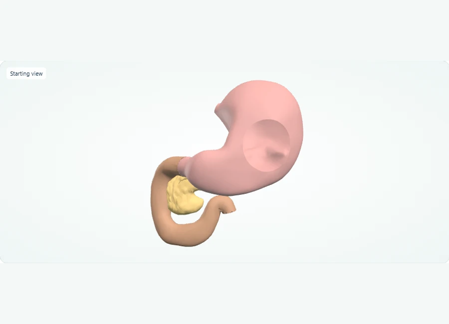
Rotate, isolate structures, and test your recall.
Rotate to the front view and zoom in to see the stomach and the duodenum continuing after it.
Select the duodenum and trace its curve, noting that the pancreatic head sits within that curve.
Use 'Hide selected' on the stomach so the pancreas, lying posterior to the stomach, is fully visible; then use 'Show all' to restore the view.
Try it yourself
Which organ has its head within the duodenal curve and lies posterior to the stomach?
Show answer and explanation
The pancreas.
After the stomach comes the duodenum, and the head of the pancreas lies within the duodenal curve; the pancreas also sits posterior to the stomach, so it is best inspected after hiding the stomach.
- The duodenum follows the stomach in the digestive pathway.
- The head of the pancreas lies in the curve of the duodenum.
- The pancreas lies posterior to the stomach, so hiding the stomach improves its exposure in this model.
Illustrated practice: Pancreas and Adjacent Upper-Abdominal Anatomy
Establishes the normal spatial relationship between the pancreatic tail and the spleen that underlies the alternate-window troubleshooting technique.
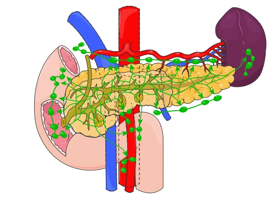
Anatomical study exhibit for the worked question below. Open the full-size view to inspect the structures.
Use the anatomical exhibit to work through the example. Choose an answer before opening the explanation.
Try it yourself
A patient is scheduled for a complete abdominal sonogram with the pancreas as a primary region of interest. The patient has not eaten for several hours. Using a curvilinear transducer, the head is visualized but the body and tail are obscured by stomach and bowel gas. Repeated graded-compression attempts in supine fail to improve the view. The anatomic exhibit (an educational illustration, not a patient scan) shows the normal pancreas in situ with the duodenum, spleen, and major adjacent vessels. Which troubleshooting approach is most likely to yield diagnostic-quality images of the missing segments? In this educational reference, green circles represent normal lymph nodes. A. Have the patient drink water to distend the stomach as an acoustic window, then image in a semi-erect or steep left lateral decubitus position and interrogate the tail through the spleen in a left intercostal approach B. Increase the time gain compensation in the mid-field and continue scanning in the same supine plane until the pancreas appears C. Increase acoustic output power to penetrate the gas, and freeze on the first frame that shows any pancreatic margin for measurement D. Measure the pancreas using the splenic vein only, because the gland cannot be imaged when bowel gas is present and the vein suffices for size assessment
Show answer and explanation
A. Have the patient drink water to distend the stomach as an acoustic window, then image in a semi-erect or steep left lateral decubitus position and interrogate the tail through the spleen in a left intercostal approach
A fluid-distended stomach provides an excellent acoustic window for the pancreatic body and tail, and repositioning lets fluid fall around the tail, which courses superiorly toward the splenic hilum; the spleen also serves as an alternate window. The exhibit makes this spatial relationship visible: the pancreatic tail extends toward the spleen, which sits adjacent to the gland and can be used as a window through a left intercostal approach. Raising gain or output amplifies noise and reverberation from gas without removing it. The splenic vein, a landmark near the gland in the exhibit, is not a substitute for visualizing the pancreas itself.
Worked Scenario: Bright Bands Behind a Fluid-Filled Structure
A paper scenario: brightness behind a fluid collection is enhancement, not a second structure; the mistake is interpreting the distal bright band as anatomy instead of as a predictable acoustic consequence.
Scenario: a paper case shows an anechoic, well-defined structure with a band of increased brightness distal to it, and a written description asks how to proceed. A plausible mistake is to report the bright band as an abnormal finding or to request more imaging of that band. The better decision is to recognize the anechoic region as a weakly attenuating fluid medium, classify the distal brightness as posterior acoustic enhancement, and note it as an expected artifact that actually supports identifying the region as fluid.
Why it matters: enhancement and shadowing are diagnostic information, not noise. The same reasoning transfers in reverse — a dark distal band behind a mobile intraluminal focus in a paper gallbladder case points to shadowing from a stone-like reflector, and the interpreter's task is to distinguish true shadowing from refraction-related edge shadowing at the neck of the structure. Practice writing one sentence for each artifact you identify stating both the cause and the conclusion it licenses.
Fixing Doppler Aliasing by Reading the Spectral Display
Aliasing is a display artifact, not disease: when the Doppler shift exceeds the Nyquist limit, half the pulse repetition frequency, the peak of the waveform wraps to the opposite side of the baseline.
The underlying physics is straightforward but easy to misapply. Pulsed Doppler samples shifts at the pulse repetition frequency, so shifts above half that value — the Nyquist limit — cannot be represented unambiguously and appear cut off and wrapped around. On a paper scenario showing a truncated, wrapped spectral peak, the plausible mistake is to label it as abnormally high-velocity flow or as turbulence. The better decision is to identify the wraparound pattern and correct the instrument.
Corrections each work through a different mechanism, so learn why, not just what: raising the velocity scale and pulse repetition frequency increases the range of representable shifts; shifting the baseline repositions the limit for a unidirectional trace; lowering the transmitted frequency reduces the Doppler shift itself; using continuous-wave Doppler removes the sampling limit entirely. Practicing the wraparound-to-cause-to-fix chain on paper makes the mechanisms stick and gives you a repeatable way to answer instrument questions — and remember angle correction choices also affect measured velocities, which is a separate decision from aliasing.
| Display finding | Most likely cause | Operator response |
|---|---|---|
| Spectral peak cut off and wrapped below baseline | Doppler shift exceeds the Nyquist limit | Raise scale/PRF, shift baseline, lower transmit frequency, or use CW Doppler |
| Mirror-image vessel on the wrong side of a strong reflector | Mirror image artifact from reflection at a bright interface | Recognize as artifact; adjust approach rather than documenting duplicated anatomy |
| Bright band distal to anechoic region | Posterior acoustic enhancement from low attenuation | Identify as artifact supporting fluid content; do not report as separate pathology |
| Dark band distal to a bright intraluminal focus | Posterior acoustic shadowing from a strong reflector | Trace the proximal path; distinguish true shadowing from edge shadowing |
Choosing Transducer Frequency and Preparing the Patient
Frequency selection is a resolution-versus-penetration trade-off: higher frequencies resolve superficial detail but attenuate faster, while lower frequencies reach depth at the cost of detail.
Because attenuation increases with frequency, a high-frequency transducer gives excellent near-field resolution for superficial structures but loses signal at depth, while a low-frequency transducer penetrates deeply with coarser detail. Train this as a decision rather than a fact: for each anatomy topic in your notes, record which frequency range serves it and why, and what you would do if a structure is deeper or larger than expected. This same logic connects to artifacts — a frequency change alters how strongly shadowing and attenuation effects appear.
Patient preparation is the other operator-controlled variable that shapes image quality. A non-fasted state can change how a fluid-filled structure distends and how bowel gas lies; a full or empty bladder changes the acoustic window for pelvic views. Study preparation as cause and effect: what the preparation accomplishes acoustically, what the image looks like when it is not met, and how the protocol adapts. Then practice naming the scanning plane and patient position for each standard view, since identifying orientation from the displayed image is a distinct skill from holding the transducer.
Applying ALARA, Ergonomics, and Documentation Standards
Professional standards in sonography mean justifying and limiting exposure under ALARA, protecting your own body mechanics, and documenting enough labeled, measured images for another person to interpret the study.
ALARA — as low as reasonably achievable — applies to diagnostic ultrasound by keeping acoustic output and exposure time justified for the diagnostic question. In practice terms: monitor the on-screen output indices, use the lowest output that yields diagnostic quality, and limit dwell time, especially in paper scenarios that present a technically difficult study with a temptation to keep scanning. The decision to stop or change approach is itself part of safe practice, not a failure of persistence.
Ergonomics is the second professional dimension: neutral shoulder and wrist positions, adjustable positioning of the examination surface, and alternating scanning technique reduce cumulative strain over a career — a standard worth knowing because professional practice is part of sonographic competence in daily work, not only image interpretation. Documentation completes the chain: correct patient and side labeling, images of measured structures, representative views of both normal and abnormal findings, and annotations that let an interpreting physician reconstruct what was seen. Treat every practice image review as documentation review too.
- ALARA: justified indication, lowest adequate output, limited exposure time, watch output indices
- Ergonomics: neutral joints, adjusted examination surface, technique variation to reduce cumulative strain
- Documentation: patient and side labels, measurements, representative normal and abnormal images, clear annotations
A Self-Check Rubric and an Adaptable Study Sequence
Grade your readiness by whether you can move from image finding to named concept to operator action, using a repeatable weekly cycle of topic review, paper scenarios, and scored self-checks.
Exercise: each week, take five unlabeled paper images or written case descriptions and, for each, write three lines — finding, concept, action — then score yourself against this rubric: 3 points means finding, concept, and action are all correct and connected; 2 means two of the three; 1 means only a definition was recalled; 0 means no usable response. Log every 2-or-lower item by concept, not by case, and let the log choose next week's review topics. These scores are learning milestones to track growth, not predictions of any exam outcome.
A realistic adaptable sequence: weeks one and two, physics foundations — attenuation, artifacts, transducer selection — with the three-step artifact check on every case; weeks three and four, Doppler and instrumentation, drilling the aliasing chain and display settings; week five, anatomy, planes, and patient preparation mapped to standard views; week six, safety, ergonomics, and documentation; final phase, mixed timed sets from the free practice bank plus weekly rubric-scored self-checks. Readiness checks: you can trace a beam path for each major artifact, fix a wrapped spectrum three different ways and say why, and state the preparation rationale for each routine study.
References and further reading
Use these references to explore the concepts and check the latest information from the relevant organizations.